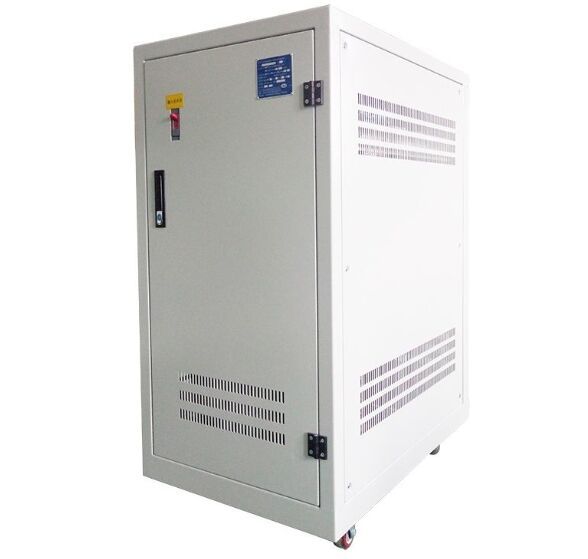
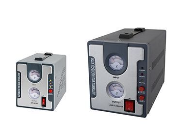
The servo-type AC voltage stabilizer is characterized in that the voltage stabilizer has an automatic regression circuit, which in turn consists of a sampling transformer, a rectifier circuit, a small time constant filter circuit, a voltage divider circuit, an operational amplifier, a drive circuit, a relay, and an energy storage circuit When the input mains power is lower than 200V and shut down or power failure, the brush will automatically return to the position close to 260V on the wire package. When the input mains is higher than 200V, whether it is shutdown or power failure, the brush will stop before shutdown status.

servo voltage stabilizer for ac
Due to the intelligent automatic return circuit, the problem of large current when starting up is completely solved, and the service life of the voltage stabilizer is prolonged. The core is an AC voltage regulating transformer (auto voltage regulator), a control circuit controls a servo motor, and drives the voltage regulator to automatically adjust the voltage. (Maintain output voltage 220v)
There are many types of household voltage stabilizers and protectors on the market, but most of them rely on relays to change the tap of the transformer to adjust the voltage. The disadvantage of this kind of voltage stabilizer is that when the mains power entering the voltage stabilizer changes(line voltage stabilizer), it will cause an instantaneous power failure, which will cause a surge current to the working appliances: a hit. The AC servo voltage stabilizer can well overcome the shortcomings of the above-mentioned voltage stabilizer.
The voltage stabilizer circuit adopts 2 groups of micro power consumption control units and 1 group of rectified stabilized power supply to form one group to reflect the control of power supply voltage increase; the other group to reflect the control of power supply voltage decrease. j1 is used to control the forward rotation of the motor and increase the output voltage of the voltage regulator; j2 is used to control the reverse rotation of the motor and reduce the output voltage of the voltage regulator.

relay type voltage stabilizer
At the same time, j1 is serially connected to the forward rotation loop to prevent the occurrence of forward rotation during reverse rotation; j2 is serially connected to the reverse rotation loop to prevent reverse rotation during forward rotation. 2 LEDs are connected in series in 2 groups of control. You can visually observe the operation of the motor (the red light is on during forward rotation, the green light is on during reverse rotation, and it is off when the voltage is normal). Use a set of better rectification and voltage stabilizing circuits to ensure the stability of the circuit. Two red and green diodes are used to indicate the control power supply.(servo regulator components of the role)
Before putting it into operation, set the action pre-values of the 2 groups of control circuits. The action value of the overvoltage control circuit is 230v, the output voltage u2 of the voltage regulator changes to 230v with the power supply voltage u, and j1 pulls in; the action value of the undervoltage control circuit is 210v2 the output voltage u2 of the voltage regulator, which follows the power supply voltage u1 , J2 pulls in when it changes to 210v. This ensures that the voltage regulator output voltage u2, at 210-230v, j1 and j2 will not act, and the motor will neither rotate forward nor reverse.
(1) When u2, with u1, changes to 230v, the voltage added to the overvoltage control circuit also rises. At this time, the overvoltage regulation loop is executed, g01 acts, the red light is on, and j1 is closed. The normally open contact j1 is closed and the motor reverse circuit is turned on, which drives the regulator's carbon brush to reverse and slide to reduce the output voltage u2. (At this time, the normally closed contact 1 is open, and the motor will not rotate forward).
(2) When u2 and u1 change to 210v, the voltage applied to the under-voltage control circuit also decreases. At this time, the under-voltage regulation loop is executed, g02 acts, the red light is on, and j2 is closed. The normally open contact j2 is closed and the motor forward circuit is turned on, which drives the regulator's carbon brush to rotate forward to increase the output voltage u2 (the normally closed contact j2 is open at this time, and the motor will not reverse).
(3) When u2, with u1, varies between 210-230v, neither g01 nor g02 will act, the red and green lights are off, and the motor will stop, which basically guarantees the regulator output u2 and voltage stabilization At 210-230v.
(4) In order to prevent the motor from continuing to rotate when the power supply voltage is too low, a micro-motion limit switch is connected in series to the j2 normally closed contact circuit, and the switch is installed at the limit position of the carbon brush. When the motor drives the carbon brush to the limit When it is in position, the upper gear top-opening micro switch installed on the shaft of the voltage regulator forces the motor to stop.