There is a main control circuit, which contains a microprocessor that controls actions. When the main circuit receives the input of the automatic voltage regulator, the signal will send feedback to the main control circuit. The microprocessor continuously receives the input voltage. If there are any fluctuations in the input voltage, the regulator will prompt the microprocessor to provide more triggers for the motor driver. The number of automatic windings on the transformer can be increased or decreased according to the servo motor. Therefore, the voltage flows to the buck-boost transformer.
The servo motor shaft is installed on the step-up and step-down transformer. Therefore, if there is any change in the voltage level across the primary coil of the buck-boost transformer, the input level in the secondary coil will change. The servo motor moves in a perfect way and the proper voltage can be observed on the primary coil of the transformer. The output voltage of the servo stabilizer is the voltage across the secondary coil of the buck-boost transformer. This process continues until the correct input voltage is reached.
In order to control the electric variable transformer, the servo stabilizer adopts an advanced servo motor concept.
After electrification, voltage correction will be delayed. When the input voltage changes up to +50%, the output voltage will be +1%. Even if there is voltage fluctuation or frequency change, the servo motor will not be damaged. Regardless of load balance and voltage balance, this working principle is applicable to all three stages, such as line-to-line, line-to-line neutral, etc. The design of the device allows it to withstand external conditions and large inrush currents, voltage fluctuations, etc. Despite the latest technology, this servo stabilizer still requires good and regular maintenance. It follows different design topologies.
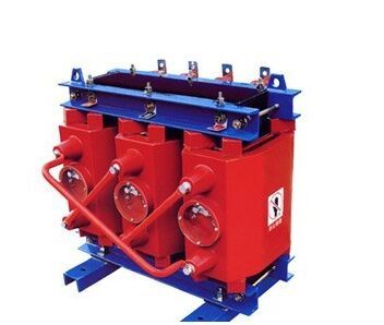
The intelligent servo transformer is an ultra-small three-phase servo transformer specially designed for the voltage mismatch between the power grid and the AC servo motor. It has changed the cumbersome, heat-generating, power-consuming, and difficult installation problems of traditional coil transformers; it does not cause pollution to the power grid. It is an ideal product to solve the problem of power adapters in industrial control systems. It is essentially different from power frequency transformers. There is also a qualitative leap forward.
Intelligent electronic servo transformers are undoubtedly special transformers for machine tools, robots, automation equipment servo systems, and servo motors. Chuangstable intelligent servo transformers have the advantages of anti-interference, enhanced heat dissipation, stability, small size, and exquisite appearance, and are the preferred servo products.

Intelligent servo transformers are dedicated transformers for servo drives. They are used to replace traditional three-phase transformers. This series of transformers solves the problems of winding transformers that are large, heavy, difficult to install, heat, easy to age, low efficiency, and expensive.
Reduce the failure rate of medical/electrical equipment.
Reduce maintenance costs(step down voltage converter: portable step down transformer)
Improve voltage/power factor.
Immediately respond to voltage transient surges
Save power consumption
Prevent fires, accidents, etc.
Protect and save human lives.
There are many real-life examples of voltage regulators. For example, it can be seen in power circuits that provide power to all other electronic and electronic circuits. Usually, a 7805 regulator is plugged in to provide power to the microcontroller-based project kit. The reason for using it is that the operating voltage of the microcontroller is 5V. The first two digits in the 7805 stabilizers represent a sequence of positive numbers, and the last two digits are used to understand the output voltage value.