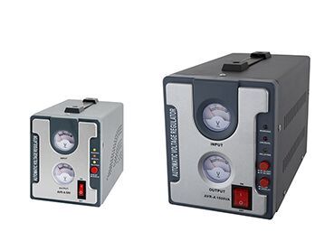
The induction voltage regulator uses the principle of electromagnetic induction to feed the primary electric energy to the secondary through magnetic field induction, and by changing the relative angular displacement of the stator and rotor winding axes and a certain connection mode, the secondary load voltage can be larger in the charged state. Within the range of smooth and continuously adjustable electrical products.
It is suitable for all kinds of loads that require voltage regulation. Non-contact adjustment, long service life, and good safety performance. The overload capacity is stronger than that of the general column type regulator. The induction voltage regulator has fast heat dissipation and cooling properties. The product runs reliably and is convenient to use and maintain.

There are two types of induction voltage regulators: three-phase and single-phase. The induction voltage regulator can continuously adjust the output voltage steplessly, smoothly, and continuously under load. It is mainly used for electrical and electronic testing, electric furnace temperature control, rectification equipment matching, generator excitation, etc. It is used as a piece of general-purpose equipment for regulating voltage in machinery manufacturing, chemical, textile, communications, laboratory, shipbuilding, agriculture, national defense, military, and other industries.
The structure of the voltage regulator is similar to a general wire-wound asynchronous motor, but because it is often working under braking, its principle of action is actually similar to that of a transformer. The pressure regulator is equipped with a worm gear transmission mechanism to make the rotor produce angular displacement, or make the rotor brake.
When the relative angular position of the rotor changes, for a single-phase voltage regulator, the interlinked magnetic flux between the stator winding and the rotor winding is changed, and the induced potential of the secondary winding is changed; for a three-phase voltage regulator, it changes The phase of the induced electric potential on the stator winding and the rotor winding, and the auto-coupling circuit connection surface makes the output voltage also obtain smooth and step-less changes.
A voltage regulator is a device that stabilizes the output voltage. All voltage regulators use the same technology to achieve a stable output voltage. The output voltage is sampled by a voltage divider connected to the inverting input of the error amplifier, and the non-inverting input of the error amplifier is connected to a reference voltage Vref. The reference voltage is generated by the bandgap reference source inside the IC. The error amplifier always tries to force its inputs to be equal. To this end, it provides load current to ensure a stable output voltage.
The voltage regulator is manual. When the voltage is low, it is manually boosted, and when the voltage is high, it manually returns to the non-boost position. The voltage stabilizer is an automatic voltage regulator. The circuit uses the output voltage as the reference frame.