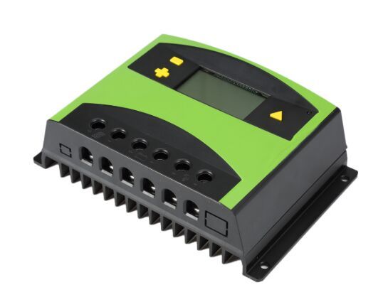
A Single-phase AC controller (voltage controller) is used to change the value of AC voltage after changing the AC voltage. The working principle of the single-phase AC motor speed controller is to connect a bidirectional thyristor in series in the motor control loop to control the conduction angle of the thyristor to control the terminal voltage of the motor.

The AC voltage controller (AC line voltage controller) is used to change the RMS value of the AC voltage applied to the load circuit by introducing a thyristor between the load and the constant voltage AC power supply(three-phase voltage regulator: automatic voltage regulator). By controlling the firing angle of the thyristor in the AC voltage controller circuit, the RMS value of the AC voltage applied to the load circuit can be controlled.
In phase control, the thyristor is used as a switch to connect the load circuit to the input AC power supply during a portion of each input cycle. That is, in a part of each input cycle, the AC power supply voltage is chopped using a thyristor.
The thyristor switch is turned on for a part of each half-cycle so that the input power voltage appears across the load, and then turned off during the rest of the input half-cycle to disconnect the AC power supply from the load.
A large-capacity capacitor is connected in series with the start winding. When the running winding and the start winding pass single-phase alternating current, the current in the start winding is 90 degrees ahead of the current in the running winding due to the action of the capacitor and reaches the maximum first. value.
Two identical pulsed magnetic fields are formed in time and space so that a rotating magnetic field is generated in the air gap between the stator and the rotor. Under the action of the rotating magnetic field, an induced current is generated in the motor rotor, and the current interacts with the rotating magnetic field. The electromagnetic field torque causes the motor to rotate.
When the external power supply voltage or load fluctuations cause the speed to change, the output signal of the speed generator coaxially connected with the motor is compared with the given speed signal through the integrator, and the error is amplified and the zero-crossing trigger signal is driven by the phase shift trigger to realize the voltage Automatically adjust so that the speed is stable at the given value. When you need to change the direction of rotation, you only need to exchange the forward and reverse joints of the motor.